Dynamic Routing Table (DRT)
The DRT is a novel concept utilized in swarm technology to maintain peer-to-peer (P2P) connections. In this approach, group members establish a graph of nodes, each identified by a unique hash, and these nodes must be interconnected.
Therefore, we require a structural framework that accomplishes the following objectives:
Maximizes the number of connected nodes at all times.
Minimizes message transmission times.
Reduces the number of links between peers.
Requires minimal computational resources.
Several solutions have been proposed to achieve these goals:
Each node is connected to the next node, resulting in only ‘N’ connections. However, this approach is not efficient for transmitting messages since the message must traverse all peers one by one.
Every node is connected to all other nodes, leading to ‘N x N’ connections. This configuration is effective for message transmission but demands more resources. This option will be selected for the first version.
An alternative solution is presented in the paper titled [Maximizing the Coverage of Roadmap Graph for Optimal Motion Planning](https://www.hindawi.com/journals/complexity/2018/9104720/), which offers optimal motion planning coverage but necessitates significant computational calculations.
Utilizing the DHT (Distributed Hash Table) algorithm for the routing table, which effectively addresses all four points and is already employed by Jami in their UDP implementation.
Additionally, to optimize the number of sockets, a socket will be allocated by a ConnectionManager to enable multiplexing sockets with a specific hash. This means that if there is a need to transmit multiple files and engage in a chat with someone, only one socket will be utilized.
Definitions
Notations:
n: Node identifier
N: Number of nodes in the network
b: Configuration parameter
Terms and Concepts:
Mobile Node: Some devices in the network can establish dynamic connectivity, allowing them to quickly connect and disconnect to optimize battery usage. Instead of maintaining a dedicated peer-to-peer socket with these devices, the protocol opts to use existing sockets if available or relies on push notifications to transmit information. These nodes are marked with a dedicated flag in the protocol.
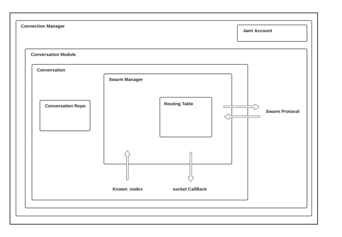
Bucket: This class is used to manipulate and store connections and to manage the state of nodes (connecting, known, mobile). Known nodes are used when the connection with a node goes offline.
Routing Table: It is employed to organize buckets, enabling the search for nearest nodes and establishing the link between the swarm manager and the DRT (Distributed Routing Table).
Swarm Manager: This component is responsible for managing the internal logic and overseeing the distribution of connections within the network.
Swarm Protocol: It is used for data exchange between peers. The following types of data can be exchanged:
Request (e.g., FIND): Query | num | nodeId
Response (e.g., FOUND): Query | nodes | mobileNodes
Message: Version | isMobile | Request or Response
Algorithms comparison
Chord
In a Chord network, each node is associated with a unique key computed using either SHA-1 or MD5 hash functions. The nodes are organized into a ring in increasing order, and each node maintains a routing table that stores information about its nearest nodes. Each entry i in the routing table contains nodes with keys such that \(hash = (n + 2i - 1) mod 2^m\), where m represents the number of bits in the key.
Every node is aware of its successors and predecessors in the Chord network.
To retrieve data, a node sends a request to its immediate successor. If the node possesses the required key, it responds; otherwise, it forwards the request to its own successor.
When adding a new node to the network, the node broadcasts messages to other nodes to update their routing tables and ensure proper integration.
If a node goes offline, it must update its routing table to reroute traffic through other available nodes.
The distance between two nodes is: \(d(n1,n2,) = (n1-n2) mod 2b`\)
The routing table size is: \(log{N}\)
The number of hops to get a value is: \(log{N}\)
Sources: (Stoica, Morris, Karger, Kaashoek & Balakrishnan, 2001). (Liben-Nowell, Balakrishnan & Karger, 2002).
Pastry
In a Pastry network, each node is associated with a 128-bit identifier generated from a hashing function. Pastry is commonly used with IP addresses, and nodes are organized in a ring with increasing order. The routing table is divided into segments, typically determined by \(128 / 2b\), where \(b\) is typically set to 4, and IP addresses are placed within these segments.
When a message needs to be transmitted to a leaf node, it is sent directly to the intended recipient. If the message is not intended for a leaf node, the network attempts to locate the nearest node and forwards the data to that node for further transmission.
Distance is: \(d(n1,n2,) = (prefix(n1) - prefix(n2)) mod 2b\)
Size of the routing table: \((2b - 1)log{_2}{N}\)
Number of hops to get a value: \(log{_2}{N}\)
where b is generally 2.
Sources: Tirée de Castro, Druschel, Hu, Rowstron (2002, p.3)21
Kademlia
This algorithm is used by BitTorrent and Ethereum. In this scheme, each node is assigned a 160-bit identifier, and nodes can be organized in a ring with increasing order. Data is stored in the nearest nodes. However, the routing table employs a binary tree structure with k-buckets (where k represents the number of nodes in each bucket) to store information about the nearest nodes.
When a node connects to the DHT (Distributed Hash Table), it attempts to populate the routing table by inserting discovered nodes into appropriate buckets. If a bucket becomes full, a node may be ignored if it is too distant; however, if the bucket represents the nearest available, it will be split into two to accommodate the new node. When a new node is added, its routing table is queried to obtain information about the nearest nodes.
To retrieve a specific value, a node sends a request to the nearest node with the corresponding hash.
Distance is \(d(n1, n2,) = n1 XOR n2\)
Size of the routing table: \(K \times log{_2}{N}\)
Number of hops: \(log{_2}{N}\)
where b is generally 1.
Implementation
When starting Jami, every conversation initiates the creation of its routing table. The initial step is to establish contact with a first node to begin synchronization with other nodes. This process is known as “bootstrapping” and consists of two main parts.
The first part involves retrieving all known devices in a conversation. This is accomplished by checking for known certificates in the repository or verifying the presence of certain members on the DHT (Distributed Hash Table). If a TCP connection already exists with any device in the conversation, it will be utilized. Additionally, known nodes are injected into the routing table.
The routing table is subsequently updated whenever an event occurs on a node.
During routing table updates, the component will attempt to establish connections with new nodes if necessary. The decision to connect to new nodes is determined by the following conditions: - For the nearest bucket, a connection attempt is made if \((maxSize(Bucket) - connected nodes - connecting nodes) > 0\). - For other buckets, a connection is initiated if \((maxSize(Bucket) - connecting nodes) > 0\).
The distinction lies in the fact that, in the case of the nearest bucket, the goal is to attempt to split buckets if required while compensating for disconnections in other buckets. This is essential to maintain knowledge of the nearest nodes.
Upon connecting to a new node, a “FIND” request is sent to discover new identifiers nearby and identify all mobile nodes. Subsequently, a “FIND” request is sent every ten minutes to keep the routing table up to date.
The primary class responsible for this process in the codebase is SwarmManager, and the bootstrapping phase is handled within the conversation’s section.
Architecture
Perfomance analysis
Tools
To validate the implementation and performance of the DRT component, we have developed several tools located in daemon/tests/unitTest/swarm, including swarm_spread, bootstrap, and more.
To interpret the results, we utilize the following tools:
gcov for test coverage analysis.
ASan to check for memory leaks and heap overflows.
gdb for debugging internal structures.
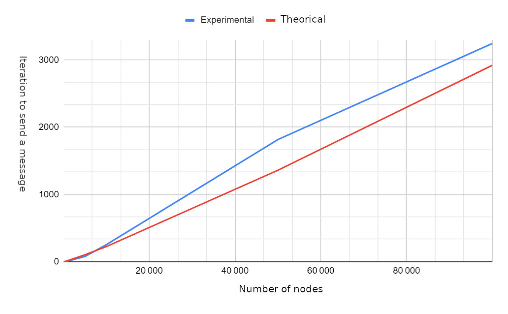
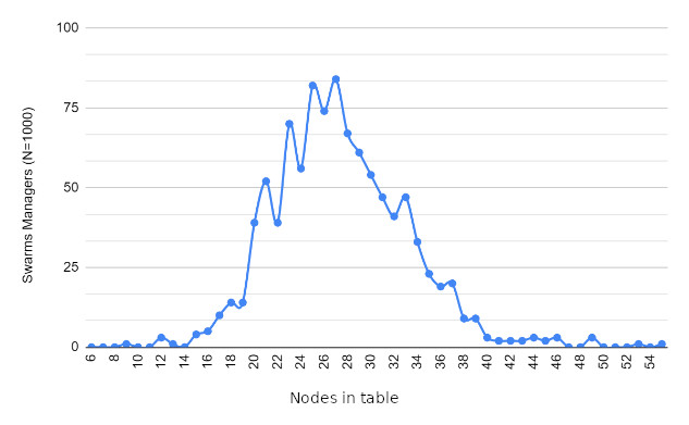
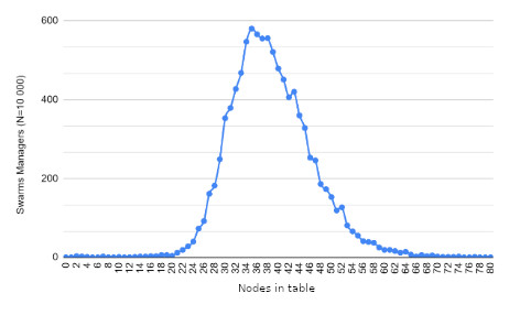
While the major focus is on unit tests, for performance analysis, we rely on swarm_spread to assess various aspects, including:
The number of hops required for message transmission.
The number of messages received per node.
Determining the maximum and minimum messages received by each node.
Calculating the iterations needed to transmit a message to all nodes.
Measuring message reception times.
Results
Future work
Dynamic bucket size limit to get different bucket size depending on how large is the routing table
Declining some connections to speed-up the transmission a bit